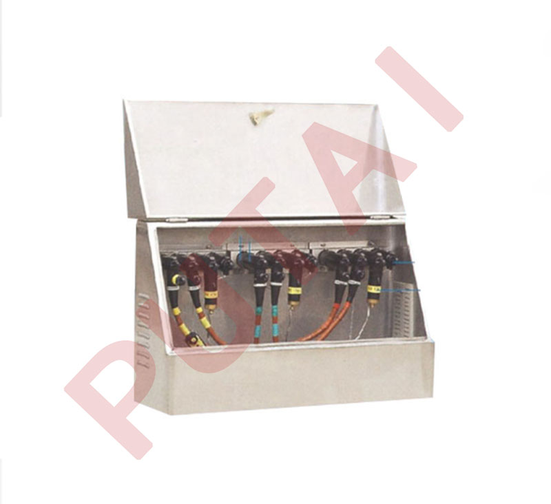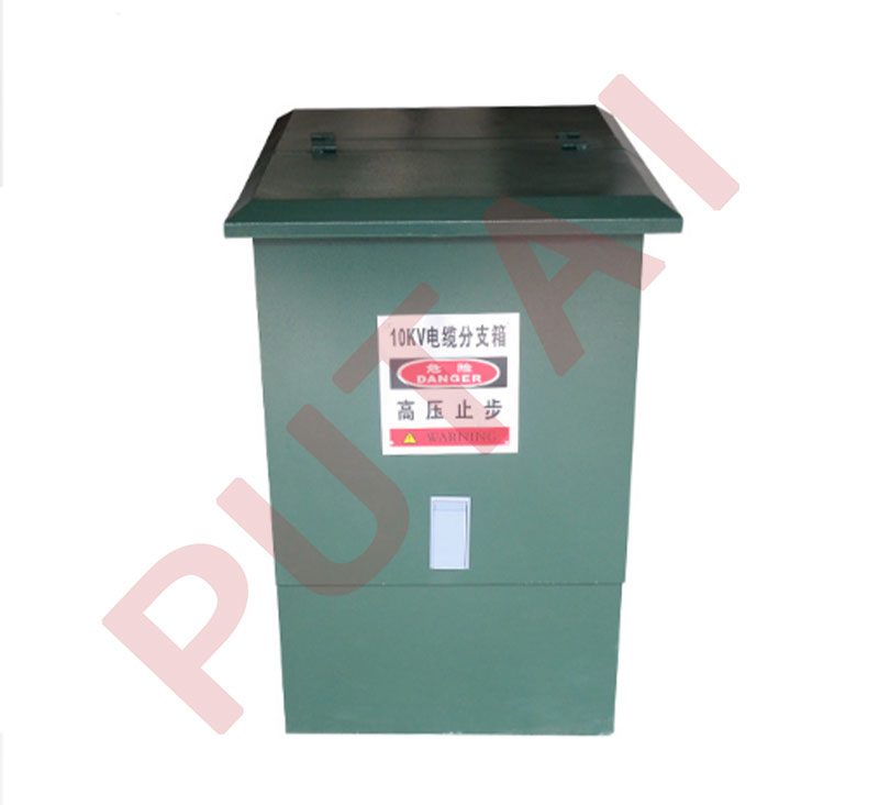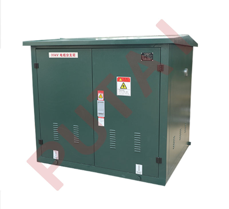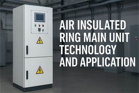


The high-voltage gas-insulated ring network cabinet cable branch box is designed for 10kV power systems, suitable for systems that are either ungrounded or grounded through small resistance or arc suppression coils. It is primarily used in power distribution systems for branching and connecting cable networks. The design of the equipment meets the requirements of harsh environments and high reliability, using high-quality materials and technology to ensure stable operation under various climatic conditions. The design of the equipment meets the requirements of harsh environments and high reliability, using high-quality materials and technology to ensure stable operation under various climatic conditions.
The device has excellent seismic resistance, capable of withstanding ground acceleration and vibrations. Additionally, it features high protection levels, effectively preventing the impact of dust, pollutants, and chemical deposits. The operating temperature range of the device is from -25°C to +40°C, and it has excellent moisture resistance, making it suitable for environments with high humidity.
| Type | Cable Branch Box,Switching Station |
| Rated Voltage | 12 kV |
| Rated Frequency | 50 Hz |
| Rated Current | 630 A, 200 A |
| Rated Load Breaking Current | 630 A |
| Rated Short-Time Withstand Current (RMS) | 20 kA |
| Rated Short-Circuit Duration | 3 s |
| Rated Peak Withstand Current | 50/63 kA |
| Closed-Loop Breaking Current | 630 A |
| Rated Cable Charging Breaking Current | 25 A |
| Rated No-Load Transformer Breaking Current | 16 A |
| Earthing Switch Short-Time Withstand Current/Duration | 25 kA/1 s |
| Rated Current Breaking Times | ≥200 times |
| Mechanical Life | ≥2000 times |
| Annual Leakage Rate of SF6 Gas | ≤1% |
| 1-Min Power Frequency Withstand Voltage (RMS) Between Breaks | 48 kV |
| 1-Min Power Frequency Withstand Voltage (RMS)Phase-to-Phase | 42 kV |
| 1-Min Power Frequency Withstand Voltage (RMS)Phase-to-Ground | 42 kV |
| Lightning Impulse Withstand Voltage (Peak)Between Breaks | 85 kV |
| Lightning Impulse Withstand Voltage (Peak)Phase-to-Phase | 75 kV |
| Lightning Impulse Withstand Voltage (Peak)Phase-to-Ground | 75 kV |
| Spring Operating Mechanism | Manual, upgradable to electric |
| Operating Voltage | DC 48 V, AC 220 V |
| External Insulation Resistance Ratio | ≥20 mm/kV |
| Opening Time Dispersion | <5 ms |
| Closing Time Dispersion | <5 ms |
| Main Circuit Resistance | <140 μΩ |
| Enclosure Protection Rating | PI4X |

Description:
1. The brick wall is built with M5 cement mortar, and the inside and outside of the ground are plastered with 1:2.5 cement mortar;
2. Waterproof treatment is performed when the bottom layer is below the groundwater level, otherwise water seepage treatment is performed;
3. The lintel is made of Φ6 steel bars and 20 concrete;
4. After processing and welding, the 8# channel steel base is treated with anti-corrosion (the user determines the anti-corrosion method)
5. The 8# channel steel base prevents the foundation notch and is fixed with tie bars and concrete
6. The user can choose not to make a cable well (the part in the dotted box) according to the specific conditions of the construction site
| plan | Outdoor intelligent switchgear (outdoor ring network cabinet) | |||
| 01、05、09 | 02、06、10 | 03、07、11 | 04、08、12 | |
| a(mm) | 1010 | 1400 | 1800 | 2200 |
| b(mm) | 900 | 1100 | 1100 | 1100 |
| c(mm) | 700 | 850 | 850 | 850 |
Load Switch: The load switch in the box-type switching station uses a three-position SF6 load switch. The electrical lifespan of the SF6 load switch should meet the E3 level requirement; the electrical lifespan of the circuit breaker should meet the E2 level requirement.
Condensation Protection: In air-insulated switchgear such as PT cabinets, metering cabinets, etc., condensation protection measures are adopted (such as installing a condensation controller inside the cabinet), including the addition of a resistor heater (with a control switch).
SF6 Gas Pressure: The relative pressure of SF6 in the gas bag of the unit-type SF6 ring network cabinet should not exceed 1.4 bar. The entire pressurized casing should comply with the "sealed pressure system" requirements as specified in IEC60298, with a leakage rate of no more than 1% per year, requiring no recharging for 30 years. The pressure inside the SF6 gas chamber can be monitored via the SF6 pressure gauge.
Fuse Rating: The fuse current rating should match the load. The fuse parameters are: rated voltage 12kV, rated breaking current (effective value) 63kA. For distribution transformer protection in switching stations, it should be capable of both fuse tripping and electric tripping.
Five-Prevent Interlock Function: The box-type switching station should be equipped with a complete five-prevent interlock function. Through the control of mechanical interlock devices, the operation fully achieves the following five-prevent interlock functions:
Prevent incorrect separation or closing of the circuit breaker (load switch);
Prevent closing the isolation switch under load;
Prevent connecting the ground wire (grounding switch) under live conditions;
Prevent closing the circuit breaker (load switch, isolation switch) under the condition of a connected ground wire (grounding switch);
Prevent entering the live compartment.
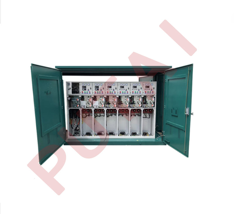
Structural Design: It adopts a fully enclosed structure. The switchgear mainly consists of the gas chamber, cable compartment, and mechanism compartment (secondary compartment). The distance from the cable joint to the cable entrance (hole or fixed clamp) is >370mm. Inner insulating supports and bushings are made of epoxy resin material, with a creepage distance ≥20mm/V. Bus connections use copper busbars, and the grounding busbar uses copper busbars, with cross-sections that meet the requirements of GB3906.
Secondary Circuit: The panel of the mechanism box is equipped with a live indicator for voltage detection, which is easy to replace, and can also be connected to a secondary phase sequence tester.
Clear Marking: The primary circuit simulation board of the box-type switching station has clear markings.
Nameplate Requirements: High-voltage electrical components installed inside, such as SF6 load switches, circuit breakers, current transformers, surge arresters, etc., should have durable and clear nameplates. The nameplates should be installed in positions that are easily observable during operation or maintenance.
Secondary Circuit Functionality: The switching station is equipped with a secondary room or control box that includes the secondary circuit compatible with the operating mechanism.
Manual/electric operating mechanisms can be configured, with provisions for electric operation functionality, remote control, and remote signal interfaces to adapt to remote monitoring requirements. It should also have short-circuit fault indicators to meet the requirements for phase-to-phase short circuits and single-phase fault grounding indicators, with switching quantity output functions. The terminals inside the ring network cabinet should use dustproof and flame-retardant products. The secondary wiring of the CT should have a copper core of 2.5 square millimeters, with a current testing box installed in the circuit. The voltage and control wiring should have a copper core of 1.5 square millimeters.
Observation Window: The lower cabinet door is equipped with an observation window made of flame-retardant transparent material.
Installation and Maintenance: The box-type switching station allows for cable installation and maintenance at the front of the cabinet and can be installed against a wall.
Three-Position Load Switch: The load switch adopts a three-position structure, and the front panel has an intuitive position indicator. The grounding switch, load switch, and isolation switch of the three-position switch have separate operation handle insertion holes. The box-type switching station structure has functions that prevent personnel injury due to internal fault arcs: metal separation plates are provided to prevent the spread of accidents; the gas chamber has a pressure relief area; and the rear part of the cabinet has a pressure relief panel.
Unified Installation Dimensions: The installation dimensions of the load switch and operating mechanism are standardized, and the same components, easily worn parts, and spare parts are interchangeable.
Gas Chamber Material: The gas chamber of the box-type switching station is made of 3mm high-quality 304 stainless steel plates welded into shape. The cabinet body is made of aluminum-zinc steel plates (except for ventilation, exhaust ports, and observation windows), with a plate thickness not less than 2mm, providing sufficient mechanical and fire resistance strength.
Protection Grade: All components in the live primary circuit are installed in the gas chamber, and the protection grade of the gas chamber should meet IP67 requirements; the cabinet body should meet IP4X requirements.
Lifting Rings: The lifting rings (one on each side) should be placed reasonably to ensure that the suspended switchgear remains level. There should be no friction contact between the lifting chain and any component to avoid scratching the surface coating of the cabinet during lifting.
Grounding Busbar: A dedicated grounding busbar should extend along the entire length of the box-type switching station. If it is made of copper, its current density should not exceed 200A/mm² during fault conditions, with a minimum cross-section of 30mm². The grounding conductor should have a fixed connection terminal connected to the grounding network, and the grounding point should be clearly marked. If the grounding conductor is not made of copper, it should still meet the peak current and short-time current withstand requirements as specified by the nameplate.
Grounding Bolt: The contact area of the grounding point of the casing should meet the requirements. The diameter of the grounding bolt should not be less than 12mm, and the grounding point should be marked with the word "Ground" or other grounding symbols.
Busbar Material: The main busbar in the gas chamber should be made of copper, and the cross-section of the busbar in the branching cabinet should be the same as the main busbar. The external surface of the main busbar and branch busbars (including connections) should be coated with organic insulation, i.e., no bare parts of the busbar should be exposed inside the busbar compartment and cable compartment (except for cable connection terminals).
Other Requirements for SF6 Load Switch:
The arc-extinguishing and insulating medium for the load switch is SF6 gas;
Each independent SF6 gas chamber should generally be equipped with a device that displays the internal gas pressure, which should clearly indicate the safe operating pressure range of the equipment.
◇ Altitude: ≤ 1000m;
◇ Maximum ambient temperature: +40℃;
◇ Minimum ambient temperature: -25℃;
◇ Maximum daily temperature variation: 25℃;
◇ Indoor relative humidity: daily average < 95%, monthly average < 90%;
◇ Earthquake resistance: horizontal ground acceleration of 0.2g; vertical acceleration of 0.1g acting simultaneously. Resonance, sine, and wave pulse testing methods are used; excitation occurs 5 times, with 5 waves per test and a 2-second interval between each, with a safety factor no less than 1.67;
◇ The installation site should be free from gases, vapors, chemical deposits, dust, dirt, or other explosive and corrosive substances that would significantly affect the insulation of the load switch;
◇ Used in ungrounded systems and 10kV systems grounded through small resistances or arc suppression coils.
This product complies with the latest national standards, industry standards, and IEC standards. After consultation and agreement with the user, other higher-performance standards may be used. The relevant clauses of the following standards are incorporated by reference into the technical conditions of this product. All standards are subject to revisions, and this technical specification conforms to the requirements of the latest versions of the following standards:
GB 16926-1997: AC High-Voltage Combined Switch-Fuse Apparatus
GF 3804-2004: 3.6kV-40.5kV High-Voltage AC Load Break Switch
GB 3906-2006: 3.6kV-40.5kV AC Metal-Enclosed Switchgear and Controlgear
GB/T 11022-1999: Common Technical Requirements for High-Voltage Switchgear and Controlgear Standards
GB 4208-2008: Enclosure Protection Class (IP Code)
IEC 420: High-Voltage AC Load Break Switch-Fuse Apparatus
IEC 298: AC Metal-Enclosed Switchgear and Controlgear for Voltages Above 1kV and Below 52kV
GB 1984-2003: High-Voltage AC Circuit Breakers