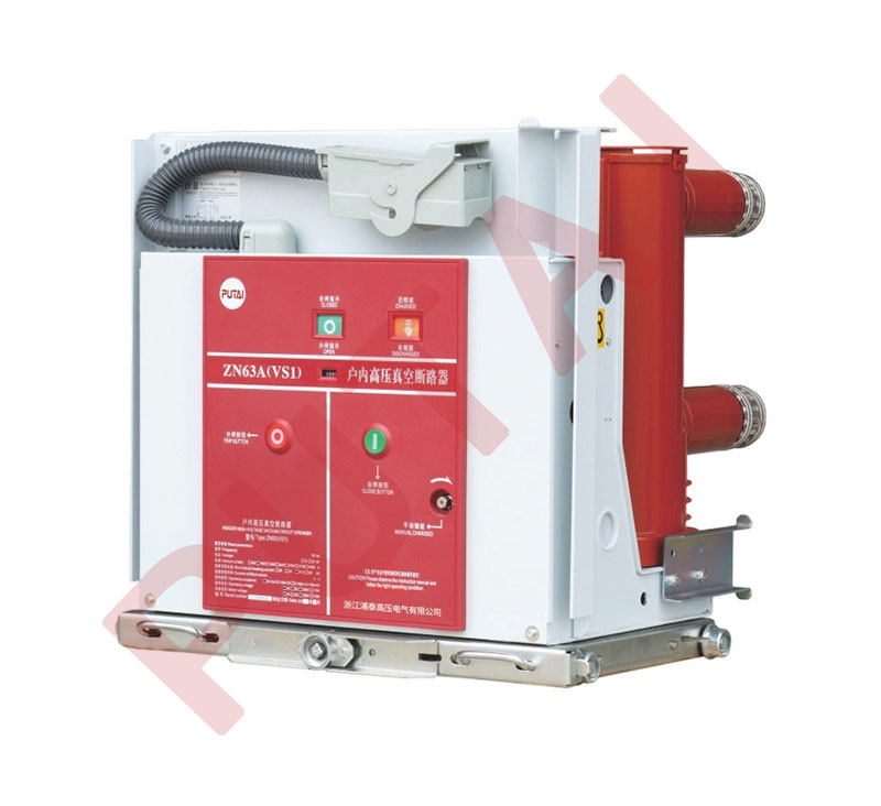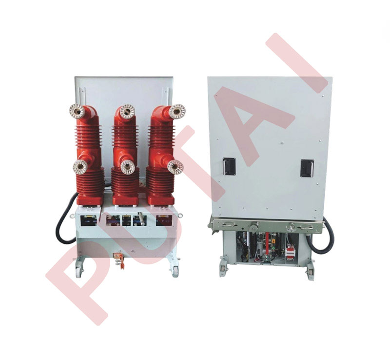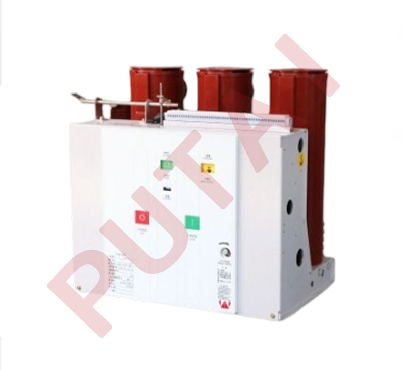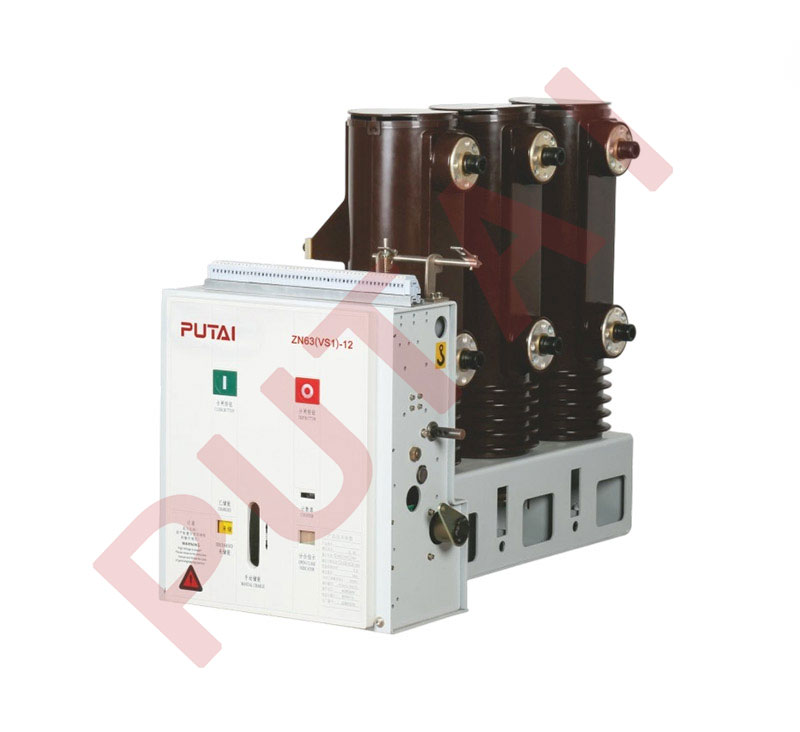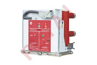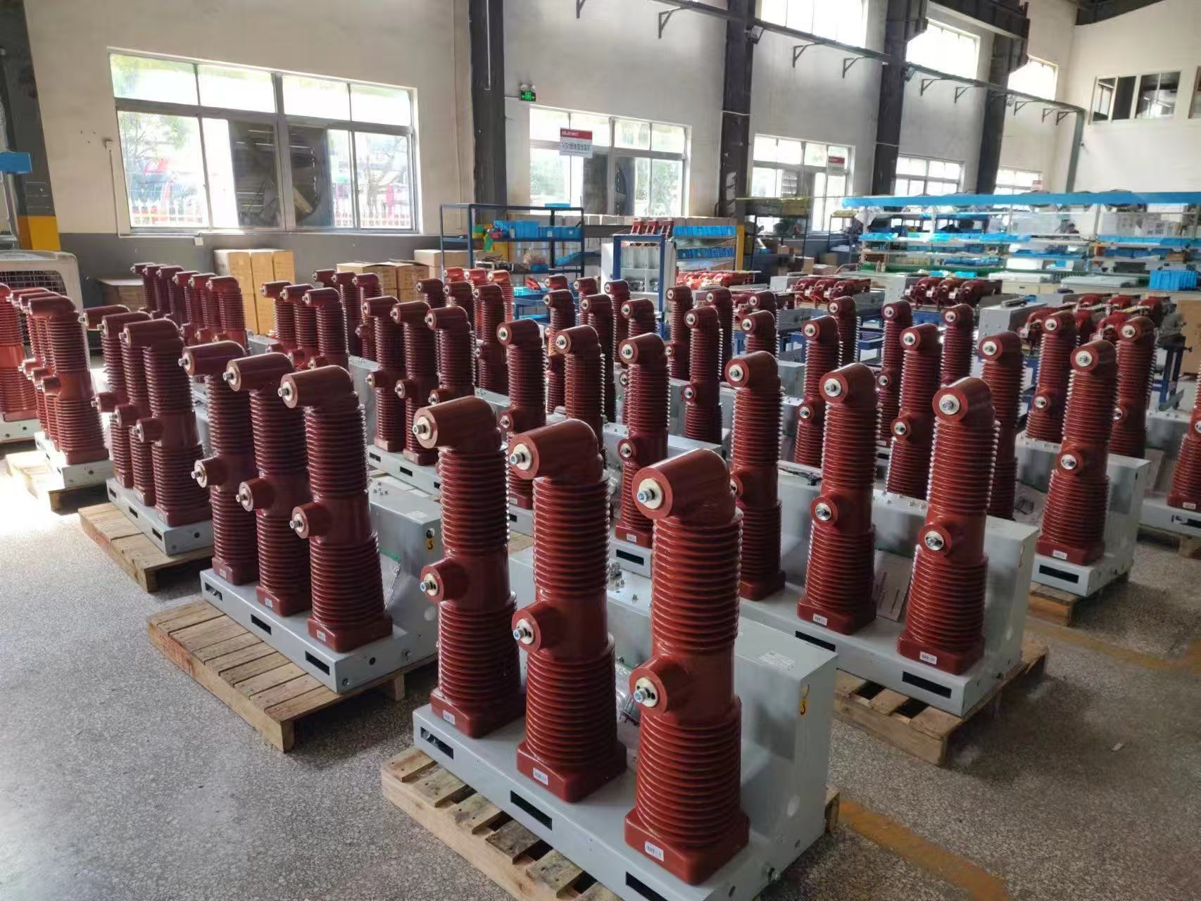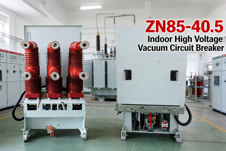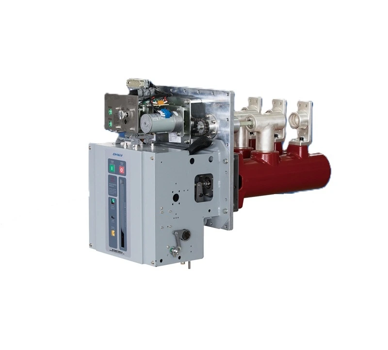


CGIS Series Indoor AC HV Vacuum Circuit Breaker is the electric system switchgear of rated voltage12kV/24kV/40.5kV. It is also as the control and protection unit of industrial enterprises and mines, power station and substation device. Circuit breaker can be proceeded frequent operation and has many times breaking and rapid reclosure capacity, and has reliable interlock function.
The CB is in line with GB/T1984-2014 "HV AC CB", JB/T3855-2008 "3.6~40.5kV indoor AC HV vacuum CB", DL/T403-2000"12kV-40.5kV HV vacuum CB ordering technical condition" and IEC 62271-100: 2008. The device is front and back split charging structure, not only as a fixed installation unit but also match handcart unit with base plate cart.
Technical parameters of CB:
| Item | Unit | Data |
|---|---|---|
| Rated voltage | kV | 12 / 24 / 40.5 |
| Rated Frequency | Hz | 50 |
| Rated 1 min power frequency withstand voltage (phase to phase, to earth, fracture) | kV | 42 / 65 / 95 |
| Rated lightning impulse withstand voltage (phase to phase, to earth, fracture) | kV | 75 / 125 / 185 |
| Rated operation sequence | — | O-t-CO-t'-CO |
| Item | Unit | Model of CB — CGIS-12/24/40.5 |
|---|---|---|
| Rated current | A | 630、1250、1250、1600、2000、2500 |
| Rated short circuit breaking current | kA | 20 / 25、31.5 |
| Rated short circuit making current (peak) | kA | 50 / 63、80 |
| Rated duration of short circuit | s | 4、4 |
| Rated breaking times of short circuit (times) | times | 30、30 |
| Mechanical Life (times) | times | 10000、10000 |
Note:20kA 25kA 31.5kA t=0.3s t'=180s
The mechanical life requirement is higher than the standard configuration, which can be manufactured through negotiation with the manufacturer.
Mechanical characteristics parameters of cb:
| Name | Unit | Parameter |
|---|---|---|
| Clearance between open contacts | mm | 12kV / 9±1;24kV / 13±1;40.5kV / 18±1 |
| Overtravel | mm | 3.5±0.5 |
| Three phase openig and closing asynchronous | ms | ≤ 2 |
| Bounce time of closing contact | ms | ≤ 2 / ≤ 3 (40.5kV) |
| Contact pressure of closing contact | N | 20kA:2000±20025kA:2400±20031.5kA:3100±200 |
| Average opening speed | m/s | 12kV / 0.9~1.3 ;24kV / 1.1~1.6;40.5kV / 1.8±0.2 |
| Average closing speed | m/s | 12kV / 0.4~0.8 ;24kV / 0.6~1.0;40.5kV / 0.8±0.2 |
Opening and closing time:
Technical parameters of tripper and latching electromagnet:
| Name | Power(W) | Rated voltage(V) |
|---|---|---|
| Opening tripper | 368 | 220/110 |
| Closing tripper | 368 | 220/110 |
| Latching electromagnet | 4.8 | 220/110 |
| Y7 (Y8、Y9)Overcurrent controller | - | - |
Technical parameters of energy stored motor:
| Rated voltage(V) | Power(W) | Energy storage time(s) | Applicable current class |
|---|---|---|---|
| 220/110 | 70 | ≤ 15 | 20kA、25kA、31.5kA |
Optional wiring deployment:
| Configuration | State of jumper wire | K-L(JP1) | J-I(JP2) |
|---|---|---|---|
| With anti-trip | With locking | √ | ○ |
| With anti-trip | Without locking | √ | √ |
| Without anti-trip | With locking | ○ | ○ |
| Without anti-trip | Without locking | ○ | √ |
Note: “○” means breaking, “√” means making
T (1-46):46 cores aviation plug
K0:Internal anti-pumping relay (optional)
Y1:Latching solenoid coil (optional)
M:Energy-storage motor
HQ:Closing trip coil
TQ:Opening trip coil
JP1-JP2:Jumper
S5:Latching solenoid micro switch (optional)
S1-S4:Limit switch (switch after closing springs charged)
QF:Auxiliary switch 10 ON 10 closed (open and close when the switch)
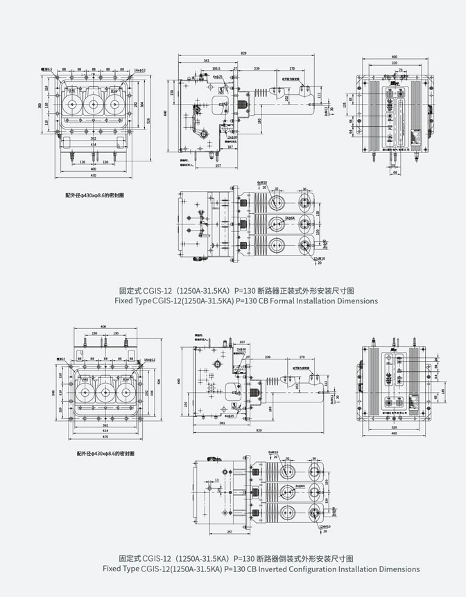
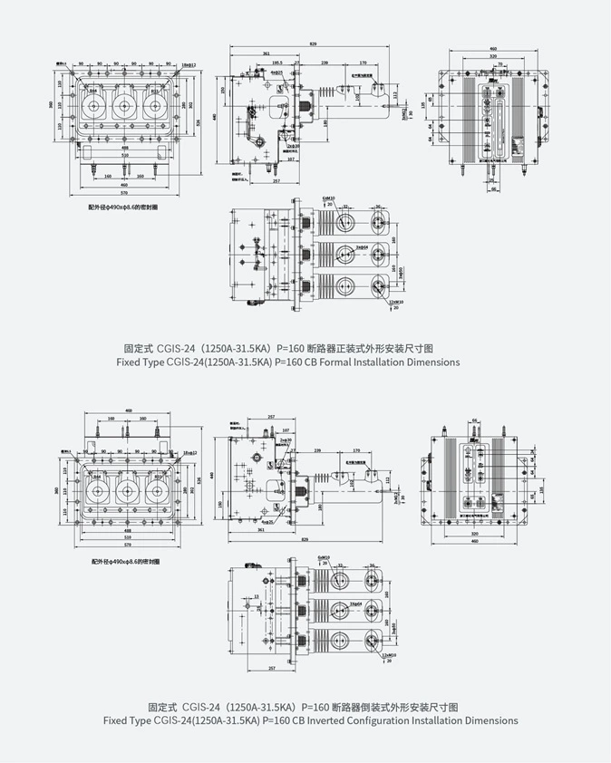
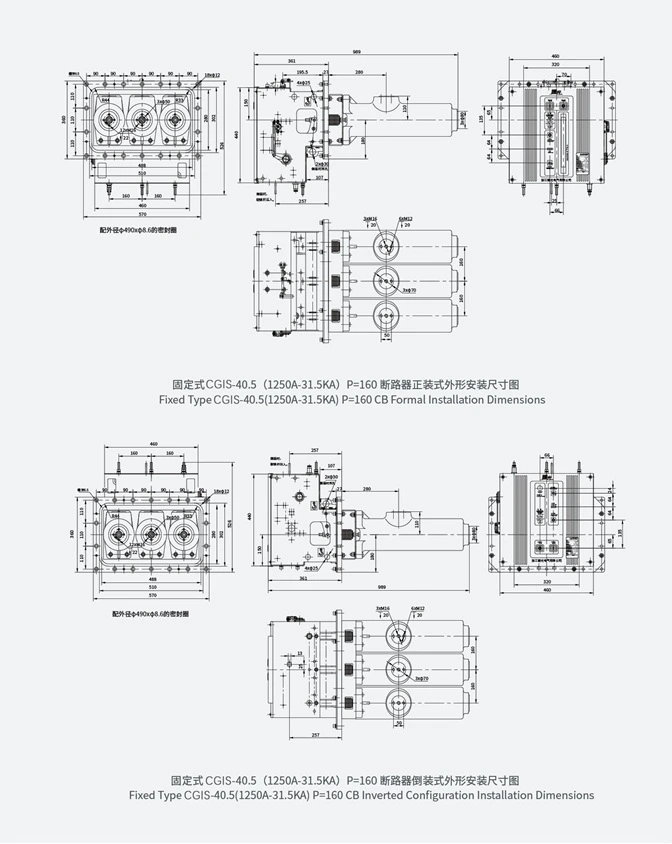
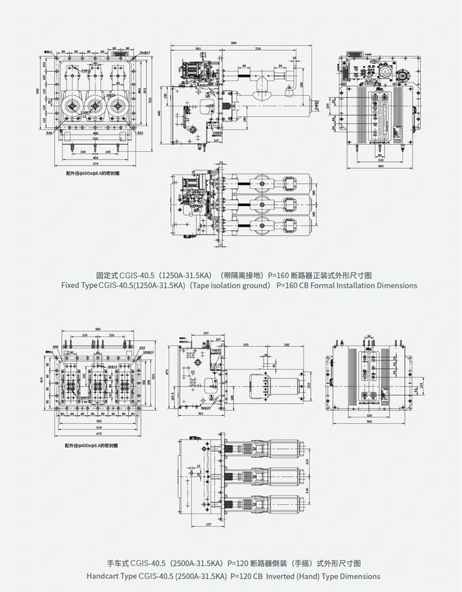
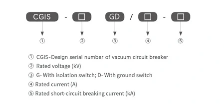
Model and Meaning:
Environmental conditions:
Special service condition:
If the customer deviates from the normal conditions, it can be consulted with the manufacturer.


 English
 Pусский
 Español